
Fixing EMC Issues in LED Street Lights: EMI & Surge Design
Nov 06, 2026
Introduction
Electromagnetic Compatibility (EMC) is a crucial bottleneck for outdoor LED street lights aiming for CE, FCC, and global market access. Operating in harsh outdoor environments, luminaires face dual challenges: high-voltage lightning surges (EMS) and high-frequency switching noise emissions (EMI).
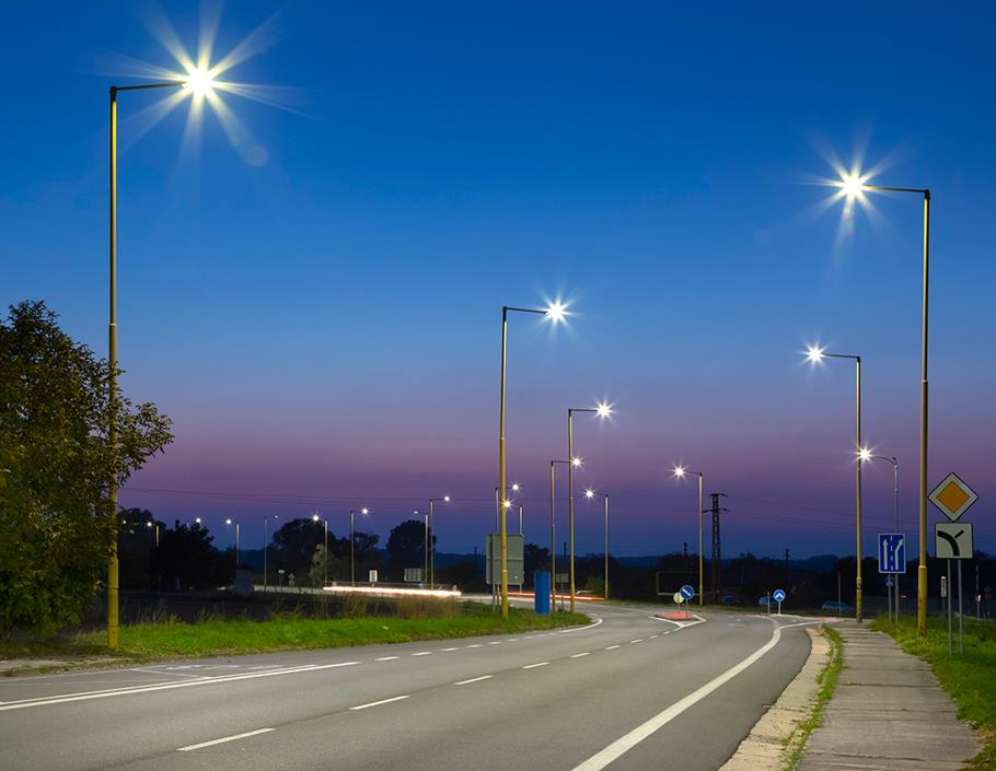
This technical guide outlines proven engineering strategies-from EMI filter design and layout optimization to multi-stage surge protection-to ensure your street lighting designs pass EMC certification seamlessly.
Key EMC Challenges & International Compliance Standards
Achieving EMC compliance requires addressing two main vectors: Electromagnetic Interference (EMI) and Electromagnetic Susceptibility (EMS).
EMI vs. EMS in Outdoor Lighting
EMI (Electromagnetic Interference):
- Conducted Emissions (CE): High-frequency switching noise fed back into the AC grid (150 kHz ➝ 30 MHz).
- Radiated Emissions (RE): Electromagnetic waves radiated into free space from cables and PCB loops (30 MHz ➝ 300 MHz+).
EMS (Electromagnetic Susceptibility):
- Surge Immunity: Resistance to high-voltage transients induced by lightning strikes or grid switching.
- ESD & EFT: Immunity to electrostatic discharge and electrical fast transients.
Mandatory Industry Standards
- CISPR 15 / EN 55015: Limits and methods of measurement of radio disturbance characteristics of electrical lighting.
- IEC 61000-3-2: Harmonic current emission limits (demanding high Power Factor Correction - PFC).
- IEC 61000-4-5: Surge immunity testing. Industrial outdoor LED street lights typically require Differential Mode ≥ 6 kV and Common Mode ≥ 10 kV surge withstand capability.
Driver-Level EMI Suppression Strategies
The LED driver is the primary generator of high-frequency switching noise. Optimizing the driver circuit is the most direct way to resolve EMI issues.
Two-Stage Input EMI Filter Design
A well-calculated AC input filter attenuates noise before it reaches the power grid:
- Common Mode Choke (CMC): Use high-permeability manganese-zinc ferrite cores to attenuate common-mode noise across the 150 kHz ~ 10 MHz spectrum.
- X and Y Safety Capacitors:
- X-Capacitors (Line-to-Line): Suppress differential-mode noise. Typical values range between 0.1 μF and 0.47μF.
- Y-Capacitors (Line-to-Ground): Bypass common-mode noise to Earth. Ensure you select safety-rated Y1/Y2 capacitors while keeping capacitance low to limit leakage currents.
Suppressing Switching Transients
High dv/dt and di/dt spikes generated by MOSFETs and rectifiers are the main drivers of radiated EMI:
- Frequency Jittering (Spread Spectrum): Modulate the driver switching frequency continuously across a narrow band. This spreads peak harmonic energy over a wider range, reducing measured EMI peaks by 3 ~ 10dB.
- Snubber Networks: Place RCD clamp circuits across primary MOSFETs and RC snubbers across output rectifiers to damp high-frequency voltage ringing.
EMI-Aware PCB Layout Rules
- Minimize High-Frequency Loop Areas: Keep the physical loop formed by the primary MOSFET, transformer, and secondary rectifier as tight as possible to minimize radiated loop antenna effects.
- Isolate Sensitive Traces: Separate low-voltage PWM dimming and sensing lines from high-voltage switching nodes. Use dedicated ground planes to shield sensitive analog circuitry.
High-Performance Surge Protection (EMS Strategy)
Outdoor street lights are exposed to severe transient voltages caused by indirect lightning strikes and grid disturbances.
Multi-Stage Surge Protection Device (SPD) Architecture
Implement a cascaded protection scheme:
- Stage 1 (Primary Heavy-Duty Protection): Integrate a combined MOV (Metal Oxide Varistor) and GDT (Gas Discharge Tube) network across AC input terminals. This stage absorbs the majority of high-energy surge currents (≥ 10 kA).
- Stage 2 (Secondary Fine Suppression): Use Transient Voltage Suppressor (TVS) diodes downstream near control ICs to clamp lingering residual voltages (residual voltage protection).
System Grounding & Chassis Bonding
Ensure the die-cast aluminum housing is bonded directly to the Protective Earth (PE) ground wire. Proper chassis grounding shields interior electronics and safely diverts high-voltage transients.
Mechanical Enclosure & Cable Shielding
Enclosure design plays an important role in controlling radiated noise:
- Die-Cast Aluminum Enclosure Shielding: Aluminum housings act as a Faraday cage. Remove non-conductive powder coatings at chassis contact seams or install conductive gaskets to ensure continuous electrical conductivity.
- Ferrite Cores & Cable Separation: Keep AC input cables away from DC output LED module wiring to prevent inductive cross-talk. Adding ferrite beads near wire entry/exit points provides extra damping for high-frequency radiation between 30 MHz and 300 MHz.
Recommended Products
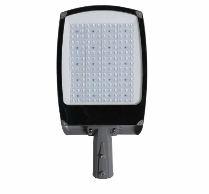
The SL15 commercial street light is available in 30–200W options, delivering 130 lm/W with AC 100–277V input. It offers a 3000–6500K color temperature range and CRI options of Ra ≥70/80/90. Equipped with SMD3030 LED chips, it features IP65 dust and water protection, IK08 impact resistance, and an adjustable mounting angle of ±15°, with vertical installation also supported.
Frequently Asked Questions (FAQ)
Q1: What Are The Primary International EMC Standards For LED Street Lights?
A: Primary EMC standards include CISPR 15 / EN 55015 (RF disturbance limits), IEC 61000-3-2 (harmonic current emissions), and IEC 61000-4-5 (surge immunity, typically requiring ≥ 6 kV differential and ≥ 10 kV common mode). Products bound for North America must also comply with FCC Part 15.
Q2: How Do You Fix Conducted Emission (CE) Failure In LED Street Lights?
A: To address CE failure (150 kHz ➝ 30 MHz), optimize the AC input EMI filter by adjusting the Common Mode Choke inductance and selecting properly rated X/Y safety capacitors. Additionally, adding an RCD snubber circuit across the primary MOSFET effectively damps high-frequency switching noise.
Q3: Why Do LED Street Lights Fail Surge Tests, And How Can They Be Protected?
A: Outdoor street lights are exposed to severe lightning transients and grid fluctuations. Protection requires a multi-stage Surge Protection Device (SPD): combine a Metal Oxide Varistor with a Gas Discharge Tube at the AC input to absorb heavy surge currents, and use TVS diodes downstream to clamp residual voltage.
Q4: Which PCB Layout Practices Effectively Reduce Radiated Emission (RE)?
A: The main rule is minimizing high-frequency power loop areas formed by the MOSFET, transformer, and secondary rectifiers. Furthermore, physically isolate AC input cables from DC output wiring, route control traces over solid ground planes, and place ferrite cores near cable termination points.
Conclusion
Solving EMC challenges in LED street lighting requires an integrated design methodology combining optimized driver schematics, disciplined PCB layout, robust surge protection, and effective mechanical shielding.
Perform in-house pre-compliance testing using a LISN (Line Impedance Stabilization Network) and near-field probes early in the prototyping phase. Catching EMI leaks before submitting samples to third-party labs will save thousands of dollars in re-certification costs and streamline your product rollout.